Movement Controlled Expression Pedal Build Guide
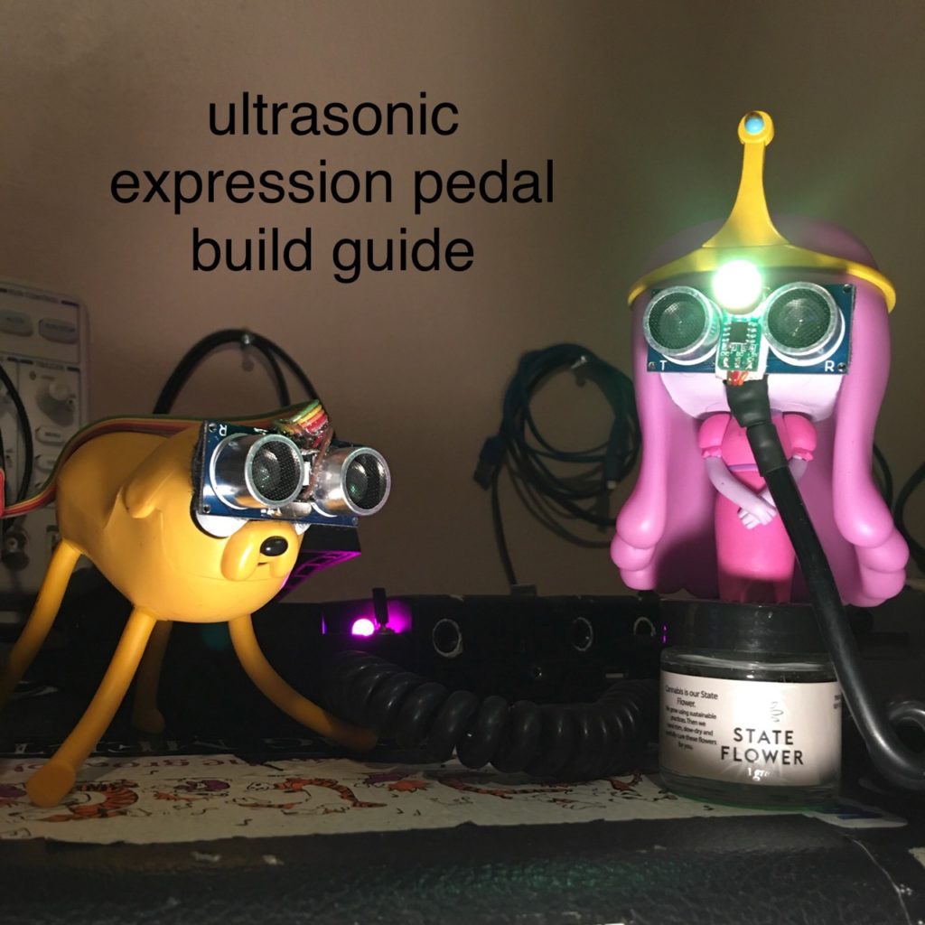
AKA “Dance-to-Wah Adaptor”
A dawless way to add distance sensors to your musical effects situation.
Photos in post above, or here.
We need distance data from the HC-SR04 ultrasonic sensor to translate into movement of the expression pedal on a guitar effects processor. In this case it’s a ZOOM G1Xon. Let’s work backwards from the result we want, toward our input action.
The original foot pedal just moves a variable resistor. Like a guitar pot, there’s three pins. (4 in this device, ignore the top one) As you move the pedal down, the middle pin gradually gets less resistance between it and the pin toward the bottom of the unit. We can tap into these bottom two pins and lower the resistance temporarily, still allowing the pedal to work normal otherwise.
All our sonar sensor does is spit a number at an arduino, which can only blink lights on and off, no analog out. “But PWM!” I hear you exclaim. Yes, we can blink a light very fast, then for each blink, we vary the time it’s on vs the time it’s off. This appears to variably dim the LED, and we use a capacitor (or two, to get about 200μF) to smooth away flickering we can’t see. This is called Pulse Width Modulation.
But now you just have analog light, what turns that into a pot? A Light Dependent Resistor of course! (aka CDS Photocell, or Photoresistor) Here’s the tedious part, you gotta make your own opto isolator now.
I started with an assortment pack of cds cells, and chose the one with the most squiggles. Compare a couple and you’ll agree there’s no better way to describe the seeing part. Long ago i tested these to have the most range with low light, the others are more for sunlight.
Now the LED to aim at it. First i tried a white LED, but at it’s dimmest, it maxed the sensor. (use white if your sensor is low on squiggles) Then i tried an old basic green one. (like in a Morley wah pedal.) First, it barely got bright enough, then it didn’t, because i partially killed it by not having the ubiquitous resistor in line. I settled with a bright clear yellow LED and a 150Ω resistor because i felt like she could take it, but 220-330 ohms is standard and more safe if your led is bright enough. Mine was only barely.
Now heat-shrink the pins of the LED and LDR, then around the LED and LDR separately, then finally in one tube together. You could just yolo them into a drinking straw, but a little wiggle will ruin your careful calibration. Congrats! you basically just made a DAC.
Now all that’s left is code, and i did that for you. There’s two numbers for the max and min brightness that you can change at the top of the code so you have a nice sweep. If it doesn’t sweep through the range smoothly even adjusting these numbers, you need to try another LED or LDR. Leave your heat shrink loose around them so you can see the LED, until you know your diy opto isolator is good. Few things feel better than a good opto isolator. Frankly, I’m excited for you.
A momentary button switches between sensitivity High, Low and Off.
Also, there’s an optional toggle switch to change to another useful mode:
It will trigger a reed relay (like a BD2A05D) that shorts the stomp switch in your pedal. When you step into a certain range, depending on the high or low sensitivity setting, it will stomp the pedal for you.
So it’s also an HC-SR04 ultrasonic distance sensor to bypass effect pedals. But mainly a motion-control movement sensor to guitar expression pedal effect build guide for music controlled by dance. I had to spell it out for good SEO ;)
I used an Arduino Pro Mini, so to program it I needed that dip socket to plug in an FTDI usb programmer. If you use a Pro Micro instead, you can just plug usb right into it.
Power it by tapping into the usb jack on the back. I used a 7805 regulator to get 5v from the 9v boss adaptor jack, then used the bottom as a heat sink. It gets a little warm and I instead recommend using a more modern regulator like the ones in car 12v USB adaptors.
You can ignore the DIP switches in the photo, those control power from the 9v or 5v internal supplies into the sensor control arduino, or the internal USB midi sound module I added. It gives me a built-in piano basically. It’s a Raspberry Pi zero running Samplerbox, a USB hub, a USB sound card, and an audio isolation transformer between the headphone jack of the USB sound dongle and the guitar effect input. These little transformers are common in car audio. Two come inside a little black lipstick box with two aux jacks, but I cracked it open. A switch disconnects the output of the transformer from the effects unit input jack, so a guitar can still plug in. There’s also a 5v regulator to use the 9v in jack, but everything could just be powered by the pedal’s original USB jack. Another switch makes the aux jack mono. I forgot to post this mod, so look forward to a breakdown of it coming soon.
Code for Arduino UNO, Pro Mini, Pro Micro, Leonardo, Donatello
// ultrasonic distance sensor to pwm an led at an ldr to vary resistance attached to a pot in a foot controller for a musical effect
// http://woz.lol
// toggle switch changes brightness at boot, and
// switches to another mode where a reed relay shorts the the bypass pedal of the effect when you get in a certain distance range

#include <Adafruit_NeoPixel.h>// add these libraries by going to
#include <NewPing.h>         // Skethch > Include Library > Manage Librarys > Search
#define MaxBri 255          // **Calibrate max brightness of opto isolator
#define MinBri 64          // **Calibrate min brightness
#define stomp 8           // this is the pin for the reed relay that stomps a pedal
#define pwmled 3         // the ldr led
#define neopin 10       // neopixel out
#define swpin 12       // toggle switch to ground
#define btnpin 11     // momentary button to ground
#define pingPin 7    // ultrasonic send pin (Trig)
#define inPin 5     // ultrasonic recieve pin (Echo)
NewPing sonar(pingPin, inPin, 200); // NewPing setup of pins and maximum distance.
Adafruit_NeoPixel strip = Adafruit_NeoPixel(2, neopin, NEO_RGB + NEO_KHZ800);
// LED #0 is on effects unit case, LED #1 is on sensor
// one 2-way toggle switch to ground, one momentary button to ground
// HC-SR04 ultrasonic distance sensor

int maxdist = 180;
int cm_new;
int cm_old;
byte mode = 2;

void setup() {
  //  Serial.begin(9600);
  strip.begin();
  strip.show(); // Initialize all pixels to 'off'
  pinMode(pingPin, OUTPUT);
  pinMode(inPin, INPUT);
  pinMode(stomp, OUTPUT);
  pinMode(pwmled, OUTPUT);
  pinMode(swpin, INPUT_PULLUP);
  pinMode(btnpin, INPUT_PULLUP);
  digitalWrite(stomp, LOW);
  if (digitalRead(swpin)) {
    strip.setBrightness(255);
  } else {
    strip.setBrightness(32);
  }
  strip.setPixelColor(0, strip.Color(128, 25, 25));
  strip.setPixelColor(1, strip.Color(128, 25, 25));
  analogWrite(pwmled, 244);
  strip.show();
  delay(1000);    //  boot test lights up everything for a sec
}

void loop() {
  sense();   // why didn't I just put this whole function in the loop? well i left you some activity space to grow and put your own sub in there to play
}

void sense() {

  cm_new = sonar.ping_cm();

  if (!digitalRead(btnpin)) {    // 3 modes, sensitivty high, low, and off
    mode++;
    if (mode > 2) mode = 0;
    if (mode == 1) {
      maxdist = 180;
      cm_new = maxdist;
      cm_old = maxdist;
      strip.setPixelColor(0, strip.Color(32, 0, 0));
    } else if (mode == 2) {
      maxdist = 90;
      cm_new = maxdist;
      cm_old = maxdist;
      strip.setPixelColor(0, strip.Color(0, 0, 32));
    } else if (! mode) {
      strip.setPixelColor(0, strip.Color(48, 12, 0));
    }
    strip.show();
    delay(400);
    while (!digitalRead(btnpin)) {}  // can't forget that debounce ;)
  }
  if (!mode) {
    strip.setPixelColor(1, strip.Color(0, 0, 0));
    strip.setPixelColor(0, strip.Color(48, 12, 0));
    analogWrite(pwmled, 0);
    strip.show();
  } else {

    int r;
    int g;
    int b;

    if (digitalRead(swpin)) {  //
      if (cm_new == 0) cm_new = maxdist;
      if (cm_new > maxdist) cm_new = maxdist;
      if (cm_new < 24) cm_new = 24;

      if (cm_new - cm_old > 10) {
        cm_new = cm_old + 10;
      }
      if (cm_new - cm_old < -10) {
        cm_new = cm_old - 10;
      }

      int cm = map(cm_new, 24, maxdist, 255, 0);
      int out = map(cm_new, 24, maxdist, MaxBri, MinBri); //adjust this at the top of the code to calibrate to your led/photoresitor action
      analogWrite(pwmled, out);   // where the magic happens

      if (cm_new != cm_old) {
        int d;
        r = cm * 3;
        g = cm * 3 - 255;
        b = cm * 3 - 510;
        if (r > 255)r = 255;
        if (r < 0)r = 0;
        if (g > 255)g = 255;
        if (g < 0)g = 0;
        if (b > 255)b = 255;
        if (b < 0)b = 0;
        strip.setPixelColor(1, strip.Color(r, g, b));
        if (mode == 1) {
          strip.setPixelColor(0, strip.Color(32, 0, cm));
        }
        if (mode == 2) {
          strip.setPixelColor(0, strip.Color(cm, 0, 32));
        }
        if (cm < 96 && cm > 88) strip.setPixelColor(0, strip.Color(0, 128, 0));
        cm_old = cm_new;
      }
      strip.show();
      delay(25);
    } else {
      strip.setPixelColor(1, strip.Color(128, 25, 25));
      if (mode == 1) {
        strip.setPixelColor(0, strip.Color(32, 0, 0));
      }
      if (mode == 2) {
        strip.setPixelColor(0, strip.Color(0, 0, 32));
      }
      if (cm_new != 0 && cm_new > maxdist / 3 && cm_new < maxdist / 2) {
        digitalWrite(stomp, HIGH);
        strip.setPixelColor(1, strip.Color(0, 128, 0));
        strip.setPixelColor(0, strip.Color(0, 128, 0));
        strip.show();
        delay(100);
        digitalWrite(stomp, LOW);
        delay(400);
        while (sonar.ping_cm() > maxdist / 3 && cm_new < maxdist / 2) {
          if (!digitalRead(btnpin)) {
            break;
          }
        }
        delay(200);
      }
      strip.show();
      delay(30);
    }
  }
}