Yamaha REX-50 Multi Effector
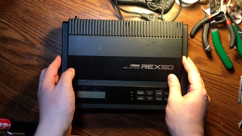
teardown tour 1987 yamaha REX50 multieffects unit (part 1) repair and upgrade
Later i’ll show you it’s sound. It’s reverb is not unlike a modern pedal but it’s pitch shifter is wacky. It’s delayed and when you add feedback it sounds like ur casting a spell. You can even adjust that delay to get an octave down accompaniment on a syncopated rhythm.
There’s a unique tone to the way this thing does distortion, an endearing lofi quality that is somehow nostalgic compared to the other brittle cereal-bowl digital distortions of the era.
stay tuned for part 2 where i talk about the weird chips inside and the unique DAC that rapidly switches between in and out at the same time, with 16bit headroom but only 31k sample rate so the frequency response is only 20-12kHz
it’s the #Delorian of #GuitarEffects, Part 2, Weird Chips and the Wacky DAC #teardown #tour #1987 #yamaha #REX50 #multieffects unit
More juicy details on that unique DAC in this thing: It has 16bit headroom but only a 31k sample rate. However, it’s claimed frequency response is only 20-12kHz. That’s odd because 31/2=15.5, (the Nyquist freq) so why isn’t the freq response up to 15.5k? Well just like Yamaha’s FM synth hardware of the era, I believe there is additional analog lowpass filtering chopping off the upper part of that range. If you hear other devices with lower samplerates, or do any rate reduction as an effect, there’s a lot of high-frequency artifacts that occur. This is a clever way to handle that. It doesn’t sound tragically lacking in treble (for me at least.) It’s not for vocals, and I don’t like painful treble in guitar anyhow.
It gets stranger, the DAC rapidly switches between handling in and out at the same time, so there may be micro high-frequency gaps in it’s sampling that I believe are part of it’s unique tone. I picture like a flange or a comb filter kinda feel to the edge of it’s highs. But I’m mainly picturing that because the Chorus and ’Symphonic’ chorus on this thing are so heartbreakingly nostalgic and luscious I swear it gives me velvet frets.
There’s also a noise gate that’s difficult to notice (thankfully) but it makes this thing spookily quiet when you aren’t playing, then you blast out of nowhere like some 80s ghost.
Speaking of treble and guitar. I never cranked that Presence knob on Fender amps. I still got my high-freq hearing you deaf bastards. Seriously, protect your hearing or you’ll be one of those old folks crankin’ treble and hurting your family.
Display Swap Reveal – Part 3 of the #Yamaha #REX50 antics extravaganza
You see these 32 character #LCD #displays in everything, since the 80s and to this day. There’s ones on ebay in every color combo. On many machines, you can swap them out without any soldering. This fella however had the pins on the side, which is less common.
The #AlesisHR-16 #DrumMachine #screen has them there too, it’s #display is definitely compatible. Several people talked about success just getting the ordinary screens with the pins on the top, and running wires to each of the pins. I wasn’t so set on the color. I just kept huntin’.
Turns out the only one I could find that fit, was also a sickly #retro #green . Like the very ooze that made, dare I say, the #NinjaTurtles .
It also happened to be the cheapest at only $7. Shout out to ebay user cb7043, they got 41 more left here: https://ebay.to/3ahz8nt
Here’s the next thing you need: power for the #backlight . I used a #Mini360 #DCtoDC Step Down Power Converter Buck Module, so they say. I let it steal power from the input pins of one of the linear regulators. I ran it’s output to the two extra pins on the screen, they were labeled LED. That little fella let me dial in the exact voltage on the spec sheet.
There was a bit more to that (foreshadowing) we’ll get into in part 5…
But next, in part 4, I’ll be revealing how I broke the original display…
What I Broke – #REX50 part 4 – In case you were wondering, here’s how I broke the previous display:
The #screen itself is a glass sandwich with an air gap behind it.
I had the bright idea of using 12V LED lighting strip and shining it at the sides of the screen, sort of into the gap behind the glass, at an angle toward the empty circuit board, behind the LCD panel. It has a milky white plastic behind it that would light up just enough, you could see it lit up this way for a test in the part 1 and part 3 videos.
This old #display had tracings that just went right off the edge of the circuit board to nothing. Maybe these were for testing before a bunch of them were cut apart. Regardless, some pins of the LED strip made contact with some of these.
Even though I had the voltage turned down to about 9 volts to dim the #LED strip, it was still plenty to fry a vertical line of an #LCD driver chip, never to be seen again.
I tried to separate them better with tape, but it was too much pressure with the case and something else had that bad touch. I then killed the dc-dc converter too. The dead converter shorted the transformer and it wouldn’t boot.
I felt like I accidentally murdered a beloved pet.
When I removed the converter, it booted fine. I kissed Rex briefly and moved on like a soldier.
I discovered you can still buy a new display for a 33 year old device. It’s interesting to see how much had been improved as well. It’s not just easier to read, but the chips are super different.
Like a musical greeting card or a kids toy, there wasn’t a board with a chip soldered to it, instead there’s just a black dot. This is called Chip-On-Board technology, where the gut of a chip (the die) is just put right on the board, with tiny wires strung to it by a robot, then covered in hard glue.
There’s more to say about this power regulator/converter situation in the next one, stay tuned for part 5…
#REX50 part 5 – Panel Gap and the Quest for Power
I was not about to take 5V power from the #7805 #regulator , that thing gets hot enough.
Linear regulators like these are a good place to look for a busted part when something digital has no power. The more they have to work to lower the voltage, the hotter they get. Cooling is often half-assed or non-existent, so adding a heat sink or fresh thermal paste is a good move. Usually you want the paste on the back of the regulator though, I only put it on the top because I wanted the bottom to get less hot on this fella, and to use more of the metal top.
It’s really cool Yamaha gave them heat sink action at all, (pun intended) but I’m inclined to say the transformer didn’t need to be such a high voltage into them. Thing is, it needed to use the parts that were available or it would be too expensive. It’s quite a nice flat transformer and very #Yamaha to have that part built-in, instead of a separate box to get lost.
While this was not the most expensive Yamaha music devices at the time, at all, it was going for what would become known as the ‘Pro-Sumer’ market, and wall-warts were not considered very ‘pro.’
This #Mini360 power converter I’m using is cheaper and more efficient than these linear regulators, so what’s the drawback? In this case it’s noise. I’ve tried to use these converters for effects pedal power supplies, and they introduce a high frequency whine to most of them. They just weren’t designed to filter it out.
Since the converter we are adding does not go near audio, just the backlight, it will give us the exact voltage we want with no extra heat. Plus I can dial in the best brightness.
There’s a bit more display drama that we left out earlier. In addition to the spacers, it is revealed that the surprise extra thickness meant I had to get progressively less nice to the old metal frame that held the previous display.
Probably time to show you some sounds, and it’s crazy pitch shifter you can control with midi-notes, see you in part 6…
#multieffect #fixup @yamahamusicusa #vintagemusic #vintagepedals #classicguitar #vintageguitar #musicstudio #recordingstudio #audioengineer #vintagegear #cyberpunk #audiorepair